How to Calculate Fiber Loss | Optical Attenuation
Learn what causes fiber optic loss and how to calculate total link loss, power budget, and margin for accurate fiber network design and performance.
How Many Fiber Connections Are Too Many:
This article examines how to calculate a fiber optic cable''s link loss budget by identifying loss sources. Testing methods using an OLTS power meter
Fiber Optics Loss Budget Calculation | Fluke Networks
You can either compare this loss value to the application requirement or calculate the expected loss based on how many connectors and splices are in the link along with the length of the fiber link and
Fiber Optic Calculator Help
The fiber optic calculator is a tool designed to assist fiber optic network engineers determine critical network design parameters. The calculator is designed to work in the 1310 nanometer wave length.
Fiber Optic Calculator
Telcordia and TIA allow a 0.3 dB maximum splice loss. Connector loss is always measured as a mated pair. ITU & IEC allow 0.5 dB loss, TIA allows 0.75 dB loss per mated pair. Splitter loss values are
Guidelines Corning Recommended Fiber Optic Test
1 Testing Tier 2 testing involves the use of an optical time domain reflectometer (OTDR) to provide a trace (visual picture) of the installed fiber optic network . Figure 2). The wavelength(s) used for
How Many Fiber Connections Are Too Many: Calculating Fiber Link
This article examines how to calculate a fiber optic cable''s link loss budget by identifying loss sources. Testing methods using an OLTS power meter or OTDR are also compared.
How to Calculate Fiber Optic Loss: Key Factors and Standards
Learn how to accurately calculate fiber optic loss to ensure optimal network performance. Explore types of loss, industry standards, and step-by-step methods for assessing link loss and power budget.
Fiber Optic Link Loss Budget calculator: Get Signal Loss 0%
Professional fiber optic link loss budget calculator. Calculate optical signal loss, power budget, link margin instantly. Free tool for network engineers with real-time analysis.
The FOA Reference For Fiber Optics
The purpose of this paper is to use simple math is to clear up this issue. Testing the cable plant Standard test methods, use a light source and reference “launch” cable on one end of the “cable
Fiber Optic Cabling Loss Limits Explained – Trend Networks
Learn about fiber optic cabling loss limits & how to calculate them. Gain insights from experts on acceptable loss for cabling projects & explore the standards.
Micro-Modular & Edge DC
Prefabricated micro-modular data centers and edge pods, scalable from 5 to 50 racks, ready for 5G and edge AI workloads.
Immersion & Liquid Cooling
Single-phase immersion cooling tanks and direct-to-chip liquid cooling switches, achieving PUE below 1.1.
AI Servers & Racks
GPU-accelerated AI servers, high-density server racks, and network cabinets optimized for AI/ML workloads.
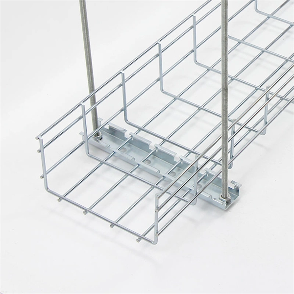
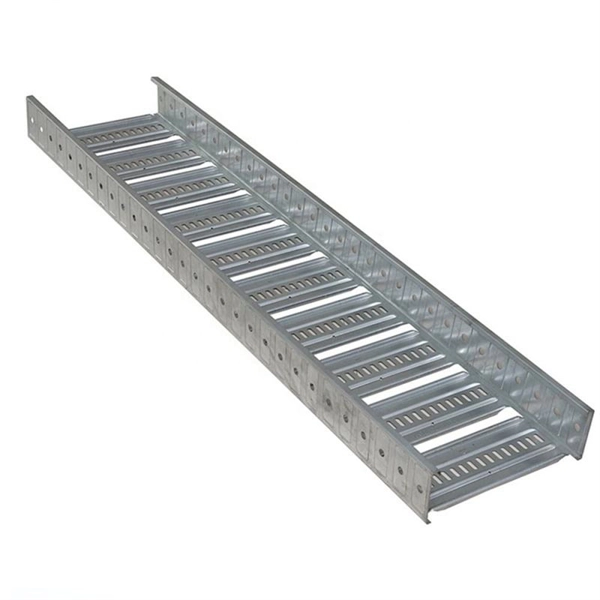
DCIM/EMS & Cable Bridge
Real-time data center infrastructure management, plus overhead cable trays and fiber bridges for structured cabling.