B-Line series Cable Tray Design Considerations
It is strongly recommended that only one cable tray splice plate be placed between support spans. Matching the tray length to your support span can help control your splice locations.
GUIDE CABLE TRAYS TECHNICAL
When fitting cable trays and their accessories, the products are cut on site to create changes of direction, adjust sections, etc. Damage can also occur during handling; as a result, both the
INSTALLATION GUIDE
Vertical cable tray elbows at the top of runs should be supported at each end. At the bottom of runs, they should be supported at the top of the elbow and within 610 mm (24") of the lower extremity of the
Cable Tray Technical Guide A practical guide to product selection
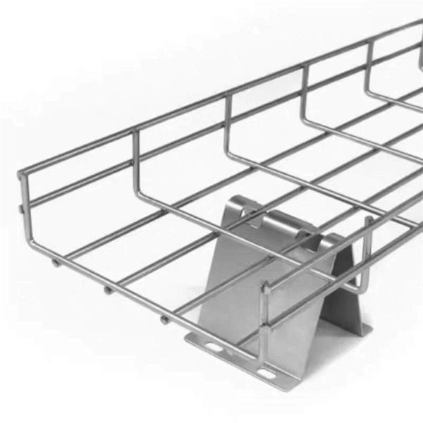
Cable tray length is selected based on the load to be supported, the distance between the supports (also referred to as the span), and handling and installation constraints.
CEC Code Rule 12-2200 CT Clearances | PDF
a. 150 mm vertical clearance, excluding the depth of the cable trays, between cable trays installed in tiers except that, wehere cables of 50 mm diameter or greater
Cable Tray Spacing Standards for Installation and Safety
Discover the essential cable tray spacing requirements for safe and efficient installation. Learn key standards, horizontal and vertical spacing, and more.
CABLE TRAY SYSTEMS GUIDE
Commonly called the Load Class, this defines the load-carrying capability of the tray for a specific support span distance. The design and cost of the cable tray is greatly affected by this designation.
Document DICOS
The cable tray should be anchored at the support nearest to its midpoint between the expansion splice plates and secured by expansion guides at all other support locations (see Figure 3-39).
Cable Tray Support Spacing: Key Guidelines Explained
Explore the essential cable tray support spacing requirements for safe and efficient installations. Learn NEC guidelines for perforated, ladder, and wire mesh trays.
NEMA BI 50016-2024
Splice plates should be placed on the outside of the cable tray, unless otherwise specified by the 778 manufacturer, with the bolt heads on the inside of the cable tray (see Figure 3-42).
Best Practice Guide to Cable Ladder and Cable Tray Systems
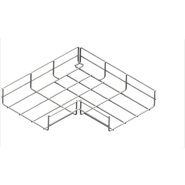
The radius for cable ladder and cable tray fittings is usually determined by the bending radius and stiffness of the cables installed on the cable ladder or cable tray.
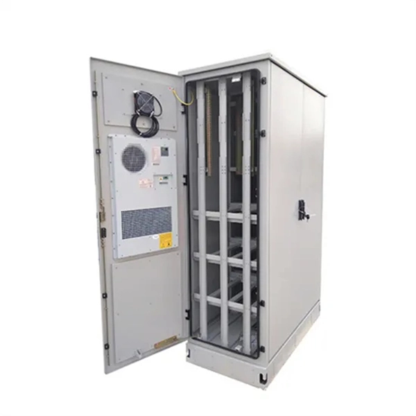
Micro-Modular & Edge DC
Prefabricated micro-modular data centers and edge pods, scalable from 5 to 50 racks, ready for 5G and edge AI workloads.
Immersion & Liquid Cooling
Single-phase immersion cooling tanks and direct-to-chip liquid cooling switches, achieving PUE below 1.1.
AI Servers & Racks
GPU-accelerated AI servers, high-density server racks, and network cabinets optimized for AI/ML workloads.
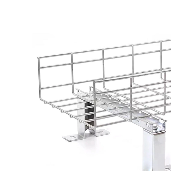
DCIM/EMS & Cable Bridge
Real-time data center infrastructure management, plus overhead cable trays and fiber bridges for structured cabling.