PC817 Optocoupler Module User Guide | Wiring & Setup
An optocoupler (also called an opto-isolator or photocoupler) is a component that transfers an electrical signal between two isolated circuits using light. Inside the package, an infrared
10 MBd High-Speed Optocoupler Design Guide
In fact, all “high-speed” optocouplers are more sophisticated versions of this simple photodiode detector circuit, in conjunction with a transimpedance amplifier and an accompanying complementary output

Using Opto Couplers
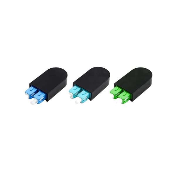
In this example a PC817 optocoupler is shown isolating a circuit using HCT logic via a 7414 Schmitt inverter gate.
6N137 High Speed Optocoupler pinout and Examples
To design an isolation circuit of a 3 to 5-volt circuit we will use some resistances and other devices will be according to the optocoupler requirement. The circuit diagram is given below:
Optocoupler Circuit Diagram
In this article, we will delve into the world of optocouplers, exploring their functioning and the various types of circuits they can be used in. At its core,
SIMPLE CIRCUIT MODIFICATIONS ENHANCE
It is the intent of this application note to present test data on circuit configurations which show improvements in the bandwidth performance of a common optocoupler.
Optocoupler Circuits, Working, Characteristics, Interfacing
OPTOCOUPLERS OR OPTOISOLATORS are devices that enable efficient transmission of DC signal and other data across two circuit stages, and also simultaneously maintain an excellent
Optocoupler Circuit Operation | Specification | Applications
The cross-section diagram in Fig. 20-35 (c) illustrates the construction of an optocoupler. The emitter and detector are contained in a transparent insulating
Optocoupler Circuit Design and Detailed Analysis
Optocoupler circuit design is not that difficult as some thought. Once you know what a CTR is and learn how to use it, then Optocoupler circuit design is that easy.
Schematic diagram of PWM optocoupler isolation circuit.
The high-speed optocoupler isolation chip selects HCPL0534, and the schematic diagram of the PWM signal optocoupler isolation circuit is shown in Figure 6.
High voltage speed optocoupler and application circuit diagram
The fast high-voltage electrical coupling in this circuit serves two primary functions: it facilitates the output voltage feedback loop in the input circuit while ensuring high-voltage isolation between low
Arduino Tutorial: HY-M154 / 817 / PC817 Optocoupler Module
This tutorial gives an introduction to the HY-M154 / 817 optocoupler module. Moreover, a simple application is programmed that shows how to wire and how to program an Arduino when
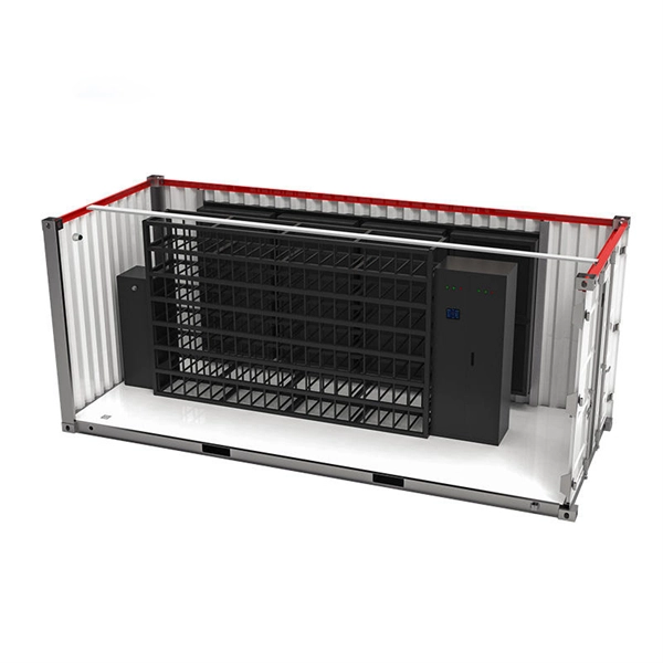
Micro-Modular & Edge DC
Prefabricated micro-modular data centers and edge pods, scalable from 5 to 50 racks, ready for 5G and edge AI workloads.
Immersion & Liquid Cooling
Single-phase immersion cooling tanks and direct-to-chip liquid cooling switches, achieving PUE below 1.1.
AI Servers & Racks
GPU-accelerated AI servers, high-density server racks, and network cabinets optimized for AI/ML workloads.
DCIM/EMS & Cable Bridge
Real-time data center infrastructure management, plus overhead cable trays and fiber bridges for structured cabling.