How to Calculate Fiber Optic Cable Attenuation: Stop
However, there is a method to determine the best fiber optic cables for your installation by performing the initial calculations—minimum distances are
Measuring Power in dB and dBm
Nor did they understand fiber optic power meters. We assume it was just to make an optical loss test set read a positive number, but it has certainly confused many people. See below. FOA has a simulator
Fiber Optic Calculator
Telcordia and TIA allow a 0.3 dB maximum splice loss. Connector loss is always measured as a mated pair. ITU & IEC allow 0.5 dB loss, TIA allows 0.75 dB loss per mated pair. Splitter loss values are
Fiber Link Loss Budget Calculator
Corning''s link loss budget calculator will calculate your total link loss and tell you if your system falls within Corning''s recommended guidelines.

Fiber Optic Attenuation Calculator | Fiberopticx
This calculator helps you estimate the total attenuation (signal loss) in a fiber optic cable link. Here are the details and instructions about each field and how they contribute to the calculation:
How to Calculate Fiber Loss | Optical Attenuation
Learn what causes fiber optic loss and how to calculate total link loss, power budget, and margin for accurate fiber network design and performance.
Fiber Optic Series: Calculating distance limits and fiber optic loss
The most straightforward and precise approach to calculate fiber loss is by conducting an Optical Time Domain Reflectometer (OTDR) trace on the given link. Performing an OTDR trace provides accurate
How to Calculate Fiber Optic Cable Attenuation: Stop Overpaying for
However, there is a method to determine the best fiber optic cables for your installation by performing the initial calculations—minimum distances are best suited for cost-effective multimode,
Signal Attenuation Calculator – Compute dB Loss in Cables, Fiber
Calculate signal attenuation in decibels (dB) for cables, fiber optics, and RF transmission lines instantly with our free online Signal Attenuation Calculator. Input cable length, attenuation coefficient (dB per
Fbb Calculator
By entering these values, users can instantly determine the total loss for a fiber optic link, enabling better system design, troubleshooting, and maintenance planning.
Fiber Performance Calculator
Calculate link or channel loss and determine the supported applications and max lengths for the configuration. The configuration and results can be exported as PDF.
Micro-Modular & Edge DC
Prefabricated micro-modular data centers and edge pods, scalable from 5 to 50 racks, ready for 5G and edge AI workloads.
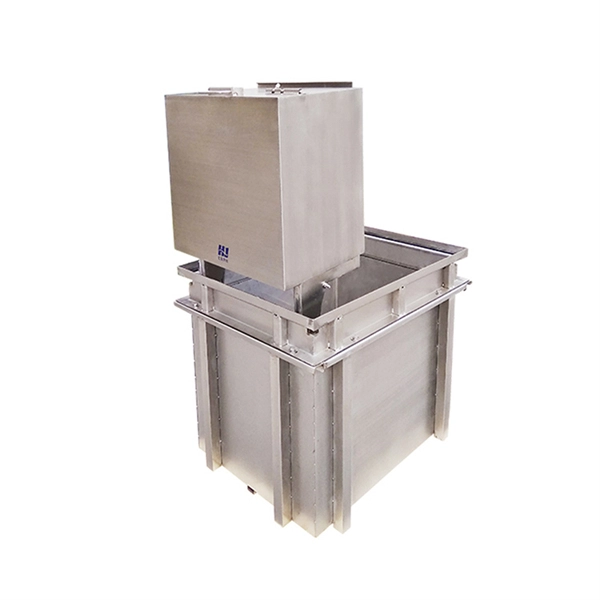
Immersion & Liquid Cooling
Single-phase immersion cooling tanks and direct-to-chip liquid cooling switches, achieving PUE below 1.1.
AI Servers & Racks
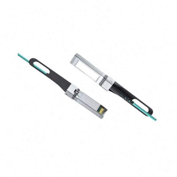
GPU-accelerated AI servers, high-density server racks, and network cabinets optimized for AI/ML workloads.
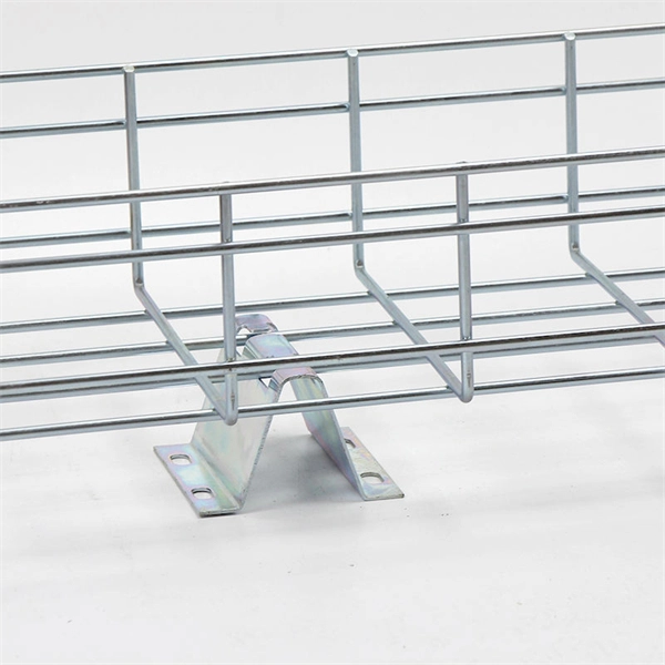
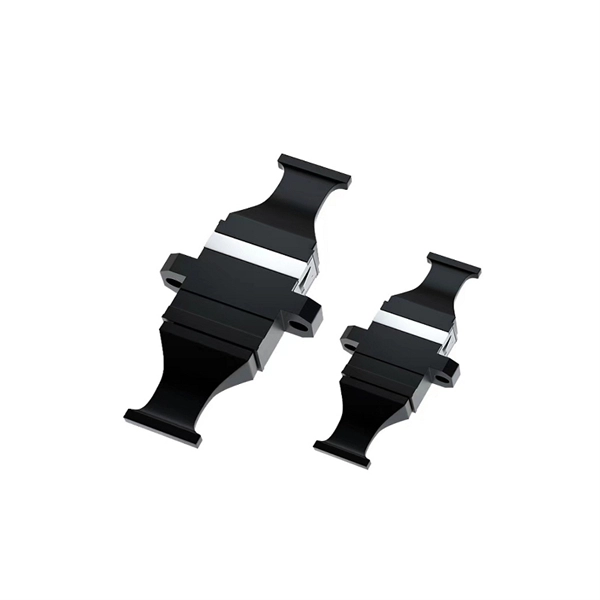
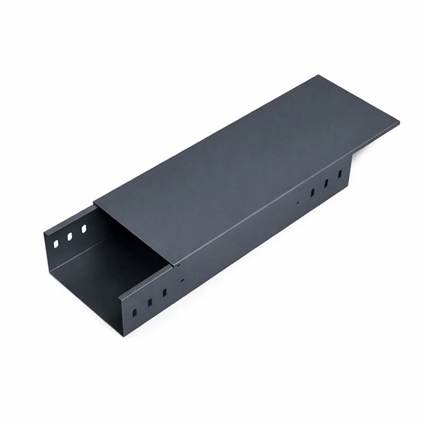
DCIM/EMS & Cable Bridge
Real-time data center infrastructure management, plus overhead cable trays and fiber bridges for structured cabling.