(PDF) Design of an automatic system for monitoring the technical
This study examines the process of monitoring the technical condition of fiber-optic cables based on the recording and analysis of changes in the pixel structure of the optical spot formed...
FOA Standard For Installing Fiber Optic Cable Plants
Since building systems may require many types of cables, both fiber and copper, these cables should be separated to protect the fiber cables from damage and all cables marked properly.
Fiber Optic Cable Installation | FiberStrike
A customized cable clip offers the ability to rapidly position the FO sensing cable against the busbar housing and achieve the desired consistent fitting of FO sensing cable across its length.
Fiber Optic Cable Installation Method
The objective of this method statement is verifying the healthiness of cable prior installation and termination of cable in panel and checking of cable
Fiber Optic Cable Installation Method | PDF | Optical Fiber
Maintaining the fiber optic cable bending radius is critical to prevent micro-bending losses and physical damage. Not adhering to the manufacturer-recommended radius can lead to attenuation issues,
METHOD OF STATEMENT FOR STRUCTURED AND FIBER
To perform OTDR (Optical Time Domain Reflectometer) testing after completed the fiber termination. The maximum loss should be less than 11db (EIA/TIA 568A Standard).
The Complete Guide to Fiber Optic Cable Management 2025
Test every fiber optic cable using industry standards and tools like OTDR and Visual Fault Locators to ensure reliable network performance. Label and color-code cables clearly following
Cable Installation Considerations for Structure Monitoring
Optimum performance for sensing objectives depends on cable type, installation method, cable position and the site environmental conditions. This applies to existing cables as well as those installed
Advanced Cable Monitoring Techniques For Earlier Failure Warning
The initial applications of distributed temperature sensing, using standard telecommunications fibre, have enabled utilities to monitor the temperature on critical cable links, pinpointing cable hotspots
Underground Fiber Optic Cable Installation: A Complete
Learn how to install underground fiber optic cables safely and efficiently. Explore trenching, conduit selection, direct burial methods, splicing,
Fiber Tester Selection Guide | Fluke Networks
A launch cable should be used between the OTDR''s port and the link under test to allow the characterization of the first connector. A tail cable should be used at the far-end of the link to allow

Optical Fiber Cable Installation Guideline
In order to effectively pull cable without damaging the fiber, it is necessary to identify the strength material and fiber location within the cable. Then, use the method of attachment that pulls most
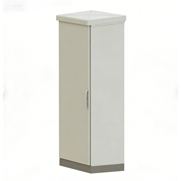
Micro-Modular & Edge DC
Prefabricated micro-modular data centers and edge pods, scalable from 5 to 50 racks, ready for 5G and edge AI workloads.
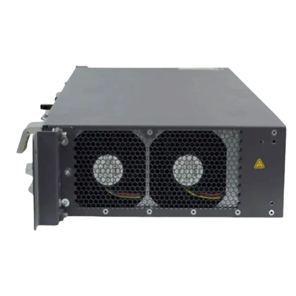
Immersion & Liquid Cooling
Single-phase immersion cooling tanks and direct-to-chip liquid cooling switches, achieving PUE below 1.1.
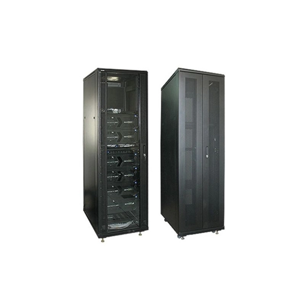
AI Servers & Racks
GPU-accelerated AI servers, high-density server racks, and network cabinets optimized for AI/ML workloads.
DCIM/EMS & Cable Bridge
Real-time data center infrastructure management, plus overhead cable trays and fiber bridges for structured cabling.