Elevation of cable trays
Generating the correct elevation of cable trays for the ortho drawings in Plant3D can be tricky. But a very simple solution is here!
To Change the Elevation of a Cable Tray or Conduit Run
Check your cable tray or conduit run to find out if you need to add more segments or change the elevation of other segments in order to reconnect the run. Optionally connect segments by adding
A Guide to Installing and Supporting Electrical Cable Trays
This guide covers the critical steps, from selecting the right electrical cable tray and performing accurate cable fill calculations to managing a safe cable pull through
CABLE TRAYS GENERAL INFORMATION AND INSTALLATION
In order to install the cable tray supports, first find the required elevation from the floor to the bottom of the cable tray and establish a level line with a laser or a nylon string.
Complete cable tray manual for electrical engineers and designers
Cable tray wiring systems are well suited for computer aided design drawings. A spread sheet based wiring management program may be used to control the cable fills in the cable tray.
How to create vertical cable tray in Revit
How to create a vertical cable tray in Revit to match the one shown in the image: This can be done with the free Revit MEP Fabrication extension. Use Revit''s built-in cable tray: Draw cable
B-Line series Cable Tray Design Considerations
A properly designed and installed cable tray system will provide outstanding reliability for a facility''s control, communication, data, instrumentation and power systems cabling & wiring. However, if cable
Cable Tray Installation Details | PDF | Electrical Wiring
The document contains engineering drawings showing dimensions and details for an elbow cable tray connector, including side views of the connector with and
Cable Tray Technical Guide A practical guide to product selection
Cable tray length is selected based on the load to be supported, the distance between the supports (also referred to as the span), and handling and installation constraints.
Modeling and Coordinating Cable Tray Systems in Revit for Electrical
Learn how to set the middle elevation, draw through the room, avoid conflicting elements, and create a detailed and clear visualization of the cable tray''s route.
Cable Tray | Design Master Software Docs
Starting Elevation: The starting elevation of the cable tray. The reference point for the starting elevation of the cable tray is set by the Vertical Alignment . Visit the Elevation section for more information.
SECTION 260536
Show fabrication and installation details of cable tray, including plans, elevations, and sections of components and attachments to other construction elements.
SECTION 26 05 36 CABLE TRAYS FOR ELECTRICAL
Designer shall provide a 12” vertical working clearance above the cable tray with no continuous obstructions. In addition, a 12” space must be provided on either side for working access.
Micro-Modular & Edge DC
Prefabricated micro-modular data centers and edge pods, scalable from 5 to 50 racks, ready for 5G and edge AI workloads.
Immersion & Liquid Cooling
Single-phase immersion cooling tanks and direct-to-chip liquid cooling switches, achieving PUE below 1.1.
AI Servers & Racks
GPU-accelerated AI servers, high-density server racks, and network cabinets optimized for AI/ML workloads.
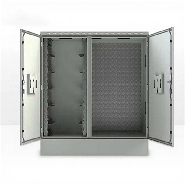
DCIM/EMS & Cable Bridge
Real-time data center infrastructure management, plus overhead cable trays and fiber bridges for structured cabling.